chitika2

‏إظهار الرسائل ذات التسميات Layer1. إظهار كافة الرسائل

الجمعة، 24 أكتوبر 2014

Lesson 8 - Ethernet and Hub Operations

Lesson 8 - Ethernet and Hub Operations

After my last conversation with my son about building the home network I promised I'd explain to him how a hub worked. And now, he's showing at the door... . So, like in the previous lessons I'll focus on the most important aspects regarding CCNA level.

In order to explain how hub works, let me talk about the Ethernet technology first. Ethernet sets the rules regarding how data coming down from the upper layers (Layers 5 through 3) should be placed on the media. It defines such transmission aspects like the maximum speed, cable type and length, connector types, how frame should be structured etc. In other words, Ethernet defines both the layer 2 and the layer 1 of our OSI model. The reason the layer 3 cannot send data directly onto the media is that there are different, disparate media types and technological limitations related to them. For instance, there will be different way of transmitting data between Ethernet switches and two computers using modems to communicate. That is why, we need the layer 2 as a "translator" so the layer 3 protocol can use different types of media without re-writing its functions. Besides Ethernet, there were other protocols in use such as Token-Ring, but today Ethernet seems to be the most commonly used solutions in local area networks (LANs).

Initially, Ethernet used coaxial cable that was terminated on both ends, and the computers were attached to the cable using so called 'T-connectors'. They shared the media, and as a result of that, they shared the available bandwidth. Today, coaxial cable is not used that often. Instead, we use UTP cable (details in the Lesson 7). But the logic of operation in both cases is quite similar.

Ethernet, using a coaxial or a UTP cable (with the hub as concentrator connecting hosts), is based on the idea that only ONE computer can transmit something at a time. Other computers will ALL receive this signal and have to wait for their turn if they have something they want to transmit (Pic 1).

Pic1. Ethernet transmissions in bus (coaxial cable) and star topology (UTP cable + hub).
Switch/router/computer icons designed by: Andrzej Szoblik - http://www.newo.pl

There is no arbiter to decide who can talk in a given time. Instead, the devices have a mechanism allowing them to 'sense' the wire to see if there is any transmission in progress. If not, they can use the media. However, if a host is already transmitting and, some other hosts "thinks" the medium is not used and starts transmitting as well, this phenomenon is called a collision. In that case, both senders will stop their transmission and wait a specified by the algorithm time before they try again. How long they have to wait is determined by so called back off algorithm. Needles to say, the more collisions occur the longer the hosts have to wait before they retransmit corrupted bits. The mechanism of checking the wire before transmission, detecting and reacting to collisions is known as CSMA/CD (carrier sense, multiaccess with collision detection).

  • Carrier Sense - "listen" to the wire to see if you can transmit.
  • Multiple Access - multiple hosts share the bandwidth and only one computer can send or receive bits but not both at the same time (half-duplex).
  • Collision Detection - in case other computer(s) started transmitting while other transmission is in progress, detect it and use back off algorithm.

The major downsides of this approach are the security (everyone "hears" everyone else), and the fact that only one computer can send data across the network at a time. What's worse, it can either transmit or receive bits (half duplex). The more computers you throw in the network, the harder is for them to get a chance to send something. Also, the chances for collisions are higher. In fact, collisions are imminent and make the system perform poorly.

HUB
A hub is a simple type of concentrator used to connect multiple computers, servers, printers etc., together. It is considered a layer 1 device due to the fact that it does not understand any headers. All it recognizes are electrical signals representing 1s and 0s. Hub operation is very simple. If signals appears on one port (interface), it is replicated on to all other active interfaces like depicted in picture 1 (right hand side).

Since hubs follow Ethernet rules in which there can be only one sender at a time, and because they transmit bits out of all remaining ports, they maintain one single collision domain.  

Pic. 2 - Hubs maintain one single collision domain.
Switch/router/computer icons designed by: Andrzej Szoblik - http://www.newo.pl

A collision domain could be defined as any group of devices which can receive transmissions from other hosts. So, hubs are not seriously considered to be a proper solution in medium/large networks. The problem with the collisions, typical in hub-based networks, has been solved by introducing another type of concentrators called bridge (old, software-based device) and switch (modern, hardware-based device) equipment used in the layer 2 of OSI mode.

Discussion on bridges and switches though, are the topic I reserve for the next lesson.

الأربعاء، 8 أكتوبر 2014

Lesson 7 - Building a Home Network

 Lesson 7 - Building a Home Network


"Dad! What are you doing?" - My son Mattie is looking over my shoulder while I'm connecting three old computers to the hub I'v salvaged from a certain death. "I'm building a small, home network." - I reply surprised at his sudden interest. "What do you need to build a small network?" - There's this little sparkle in his eyes only kids his age have. "And how do you do it?". There's nothing I can do but explain to him how it's done!

We will need few components to build this network. First of all, we'll need computers, running some operating system that can talk across the network (like Mac OS, Windows, Linux).

Pic. 1 - Computers.

Computers are already equipped with NICs (Network Interface Cards) by the manufacturer.
"What does the NIC look like dad?" - He interrupts. Nine years old kids can be very tenacious, almost obsessive. They are not easily dismissed. They won't stop unless they're fully satisfied with the answer. So, I'm taking one NIC out of the computer and explain that it is plugged in to the PCI slot in order to work. "PCI slot is connected to the motherboard of the computer and the operating system uses a special piece of software to talk to the NIC. It's called a driver. The driver translates between an operating system and the NICs hardware. The NIC sends bits down to the wire and knows what to do when bits come back from the network". Bits are small pieces of information (1s and 0s) which in software make data like music, pictures, text documents etc.


Pic. 2 - NIC (Network Interface Card).


"Okay." - Mattie says, "But what else will you need?

"I will need Unshielded Twisted Pair cables (UTP). One, for each computer. The cables (sometimes referred to as Ethernet cables), use RJ-45 connectors that the most commonly used nowadays." - I reply. "Here's the cable without the connector:

Pic. 3 - UTP cable without RJ-45 termination

"Mattie's looking at the cable and I know what's going to happen next. "Dad, why does it have so many wires and why are those twisted like that?"

One pair of the wires (two wires) are used to transmit data. Another pair, is used to receive data from the network. Other wires can be used to carry the power to some types of the devices (PoE devices) or to accomplish faster speeds (1Gbps etc.). They are twisted like that on purpose. The guy who invented that concept was Graham Bell. He invented it for the telephony purposes and patented that in 1881. He discovered that twisting wires (conductors) minimized or canceled Electromagnetic Interference (EMI) from external sources and, so called, cross talk from the neighboring wires.

The cable must be terminated at both ends with RJ-45 type of connector, like the one depicted below:

Pic. 4 - RJ-45 Connector.

Below is the cable with the connectors.

Pic. 5 - UTP cable with RJ-45 connectors.
The UTP cables can have different category numbers (CAT 1-6). The higher the category number is, the better quality of the cable, the faster, and better transmissions are going to be. Also, the UTP cables can be terminated in two different ways like explained below.

Straight-Through Cable
In straight through cable the transmitting pair of wires are 1 and 2, the receiving pair of are wires 3 and 6. There are two major standards (ways) of using the colored wires, but important thing is, that the colors on the both ends of the cable are terminated identically. Please, look at the picture below.

Pic. 6 - Straight Through Cable.


Cross-over Cable
In the cross-over cable, the position of the wires is changed such that the sending pair is terminated at the receiving pair on the other side of the cable. It is illustrated below.

Pic. 7 - Cross-over Cable

My son Mattie's holding both types of cable, looking at them and I know I cannot dismiss him with that explanation. So, I continue.

If you connected two computers together and the NICs are wired identically, you would connect the sending pair (pins 1 and 2) to the sending pair on the other end. This obviously would not work. You must connect sending pair on one end (pins 1 and 2) to the receiving pair (pins 3 and 6) on the other end. For instance, if you connect the following devices together, you'll need cross-over cable:
  • computer-to-computer
  • switch-to-switch
  • hub-to-hub
  • computer-to-router (directly)


NOTICE!
Modern NICs can 'sense' the type of cable and adjust the operation regardless of the cable used. But this is not always the case.


Devices such as hubs and switches, are designed such way they can use straight-through cables. The cross between the transmitting and receiving pairs is done in their port controllers. So, the following device connections will use straight-through cable:
  • computer-to-hub
  • computer-to-switch
  • router-to-hub
  • router-to-switch
Now, all we have to do is to connect the cables to the the hub, configure IP addresses on the NICs and voila! They can talk to one another.

Ethernet Hub
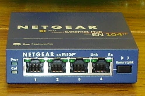
It is a simple device that allows to connect a few computers together. Look at the typical, cheap hub you can buy for home purposes:

Pic. 8 - An Ethernet Hub.

"How does the hub work then?" - I can tell my son got some interest by now.
"Well, that is the topic of our next lesson." - I say smiling.
;)