chitika2

‏إظهار الرسائل ذات التسميات Basics. إظهار كافة الرسائل

السبت، 25 أكتوبر 2014

Lesson 9 - Bridging/Switching Learning Process

Lesson 9 - Bridging/Switching Learning Process

In the previous lesson we looked at the Ethernet and a hub operation. We classified hub to be a layer 1 device as it does not understand any headers used by upper layers of our networking model. It simply forwards the bits it receives out all remaining ports. Even though, they do provide basic connectivity to our hosts, they also reveal a lot of weaknesses. For details look at the lesson 8.

A more intelligent and robust device that can replace a hub is a layer 2 switch. You've already learned how to navigate in IOS, and provide the switch with a simple configuration. With this lesson we begin a more serious exploration of layer 2 through layer 4 functions starting with Layer 2. This is good enough excuse to brush upon encapsulation/de-encapsulation process, and the structure of the headers.

Enapsulation Process Re-Visited
This is a quick review of encapsulation process I would present to my nine year old son (if he wanted to learn more).

1. Assuming that TCP session is already complete, the application is forming the request (data) which is sent down to the layer 4. Layer 4 process places source and destination port numbers in the header (Pic. 1).

Pic. 1 - Application sends data to the Transport layer.
Icons designed by: Andrzej Szoblik - http://www.newo.pl

2. Transport layer sends the segment down to the layer 3 for processing. This payload ends up encapsulated in an IP header with the source and destination IP addresses added in the header (Pic. 2).
Pic. 2 - Transport layer sends the segment to the Internet layer.
Icons designed by: Andrzej Szoblik - http://www.newo.pl

3. The layer 3 sends the packet down to the layer 2 (Data-Link) for processing. Layer 2 adds its own header (here the Ethernet header) with the source and the destination MAC addresses (Pic. 3).

Pic. 3 - Internet layer sends packet down to Data-Link layer.
Then, this whole 'thing' is converted into bits and put onto the wire.

Now, we can see what happens when the bits are sent to the port of the switch to reach the destination computer. Let's bring back the Ethernet header to see what we find in it (Pic. 4).

Pic. 4 - Ethernet Header
Icons designed by: Andrzej Szoblik - http://www.newo.pl
In this header there are two pieces of information that switches use to build their mac-address-table (CAM) and make forwarding decisions. Those are: source and destination MAC addresses. And here is how it works.
Initially, the mac-address-table (aka CAM) is completely empty (Pic. 5).

Pic. 5 - Content Addressable Memory (CAM) initially is empty.
Icons designed by: Andrzej Szoblik - http://www.newo.pl
Sooner or later, some computers begin to transmit something across the network. In my example, the PC1 (source MAC address: 1111.1111.1111) begins transmission to PC3 (destination MAC address: 3333.3333.3333). Below is the sequence of events.

1. PC1 with the source MAC address of 1111.1111.1111 sends the Ethernet frame to the destination MAC address of 3333.3333.3333 (PC3).

2. SW1 receives the frame on port F0/1. It 'reads' the source MAC address and maps it to the receiving port in its CAM (like shown in the Pic. 6).


NOTICE
Switches learn MAC addresses by reading the SOURCE MAC from the INCOMING frames (going towards the switch) only. They do not learn anything when the frame leaves the switch.


Pic. 6 - SW1 learns dynamically 1111.1111.1111 by reading the source MAC address from the incoming frame.
Icons designed by: Andrzej Szoblik - http://www.newo.pl

3. SW1 then, reads the destination MAC address and will try to find the outbound port for that destination. Since 3333.3333.3333 has not yet been mapped to any port, the switch will perform flooding (Pic. 7).

Flooding is the act of sending a frame out of all active ports except the port where the frame arrived.

There are few reasons why switch decides to flood a frame:
  • Switch does not know where the destination host is = unknown MAC address.
  • The destination MAC address is broadcast: FFFF.FFFF.FFFF.
  • The destination MAC address is multicast.
 Pic. 7 - SW1 Floods unknown destination MAC address 3333.3333.3333.
Icons designed by: Andrzej Szoblik - http://www.newo.pl

4. Computer with MAC address other than 3333.3333.3333 drop the incoming frames. PC3 is the destination of the frame so it further processes it (de-encapsulation). Meanwhile, the SW2 learns the source MAC address on the receiving port F0/12 and maps it in its CAM. Since, as of right now, it does not know where 3333.3333.3333 resides, it also floods the frame (Pic. 8).

Pic. 8 - SW2 is learning 1111.1111.1111 on F0/12 and flooding the frame.
Icons designed by: Andrzej Szoblik - http://www.newo.pl
5. PC3 (3333.3333.3333) responds the PC1 (1111.1111.1111). SW2 receives the frame sourced with 3333.3333.3333 on port F0/2. It puts this in its mac-address-table (CAM), mapping it to the inbound port F0/2. Next, it will read the destination MAC address in the frame (1111.1111.1111) and consults it with its CAM entries. It finds the outbound port F0/12 where this address has already been learned from the incoming frame. This time, the transmission is not flooded as SW2 has the mapping in the table. SW1 receives the frame on its port F0/12. It reads the source MAC address (3333.3333.3333) and maps it to the receiving port F0/12 in its CAM table. Then it looks at the destination MAC address (1111.1111.1111) and finds the outbound port which is F0/1. NO FLOODING THIS TIME on either switch! All illustrated in the Pic. 9.

Pic. 9 - Port-to-Port transmission in the reply as all MAC addresses in question have already been learned.
Icons designed by: Andrzej Szoblik - http://www.newo.pl
Since all computers 'speak' now and then, the switches will learn their MAC addresses from the incoming frames by reading the source MAC address field in the headers. They will populate the CAM and like depicted in Pic. 10.

NOTICE
All entries in the CAM table (mac-address-table) have a default aging timer which is 300 seconds (5 minutes). If the host do not refresh those entries by sending frames toward the port, the entries will be removed after 5 minutes. Of course, if the host transmits the frames again the incoming ports will map them again.


Pic. 10 - Content Addressable Memory (CAM) full.
Icons designed by: Andrzej Szoblik - http://www.newo.pl

In the next lesson we will look at Cisco Discovery Protocol.In lesson 11, we're going to put all the pieces together to show you the practical applications of what you have learned.

الأربعاء، 8 أكتوبر 2014

Lesson 7 - Building a Home Network

 Lesson 7 - Building a Home Network


"Dad! What are you doing?" - My son Mattie is looking over my shoulder while I'm connecting three old computers to the hub I'v salvaged from a certain death. "I'm building a small, home network." - I reply surprised at his sudden interest. "What do you need to build a small network?" - There's this little sparkle in his eyes only kids his age have. "And how do you do it?". There's nothing I can do but explain to him how it's done!

We will need few components to build this network. First of all, we'll need computers, running some operating system that can talk across the network (like Mac OS, Windows, Linux).

Pic. 1 - Computers.

Computers are already equipped with NICs (Network Interface Cards) by the manufacturer.
"What does the NIC look like dad?" - He interrupts. Nine years old kids can be very tenacious, almost obsessive. They are not easily dismissed. They won't stop unless they're fully satisfied with the answer. So, I'm taking one NIC out of the computer and explain that it is plugged in to the PCI slot in order to work. "PCI slot is connected to the motherboard of the computer and the operating system uses a special piece of software to talk to the NIC. It's called a driver. The driver translates between an operating system and the NICs hardware. The NIC sends bits down to the wire and knows what to do when bits come back from the network". Bits are small pieces of information (1s and 0s) which in software make data like music, pictures, text documents etc.


Pic. 2 - NIC (Network Interface Card).


"Okay." - Mattie says, "But what else will you need?

"I will need Unshielded Twisted Pair cables (UTP). One, for each computer. The cables (sometimes referred to as Ethernet cables), use RJ-45 connectors that the most commonly used nowadays." - I reply. "Here's the cable without the connector:

Pic. 3 - UTP cable without RJ-45 termination

"Mattie's looking at the cable and I know what's going to happen next. "Dad, why does it have so many wires and why are those twisted like that?"

One pair of the wires (two wires) are used to transmit data. Another pair, is used to receive data from the network. Other wires can be used to carry the power to some types of the devices (PoE devices) or to accomplish faster speeds (1Gbps etc.). They are twisted like that on purpose. The guy who invented that concept was Graham Bell. He invented it for the telephony purposes and patented that in 1881. He discovered that twisting wires (conductors) minimized or canceled Electromagnetic Interference (EMI) from external sources and, so called, cross talk from the neighboring wires.

The cable must be terminated at both ends with RJ-45 type of connector, like the one depicted below:

Pic. 4 - RJ-45 Connector.

Below is the cable with the connectors.

Pic. 5 - UTP cable with RJ-45 connectors.
The UTP cables can have different category numbers (CAT 1-6). The higher the category number is, the better quality of the cable, the faster, and better transmissions are going to be. Also, the UTP cables can be terminated in two different ways like explained below.

Straight-Through Cable
In straight through cable the transmitting pair of wires are 1 and 2, the receiving pair of are wires 3 and 6. There are two major standards (ways) of using the colored wires, but important thing is, that the colors on the both ends of the cable are terminated identically. Please, look at the picture below.

Pic. 6 - Straight Through Cable.


Cross-over Cable
In the cross-over cable, the position of the wires is changed such that the sending pair is terminated at the receiving pair on the other side of the cable. It is illustrated below.

Pic. 7 - Cross-over Cable

My son Mattie's holding both types of cable, looking at them and I know I cannot dismiss him with that explanation. So, I continue.

If you connected two computers together and the NICs are wired identically, you would connect the sending pair (pins 1 and 2) to the sending pair on the other end. This obviously would not work. You must connect sending pair on one end (pins 1 and 2) to the receiving pair (pins 3 and 6) on the other end. For instance, if you connect the following devices together, you'll need cross-over cable:
  • computer-to-computer
  • switch-to-switch
  • hub-to-hub
  • computer-to-router (directly)


NOTICE!
Modern NICs can 'sense' the type of cable and adjust the operation regardless of the cable used. But this is not always the case.


Devices such as hubs and switches, are designed such way they can use straight-through cables. The cross between the transmitting and receiving pairs is done in their port controllers. So, the following device connections will use straight-through cable:
  • computer-to-hub
  • computer-to-switch
  • router-to-hub
  • router-to-switch
Now, all we have to do is to connect the cables to the the hub, configure IP addresses on the NICs and voila! They can talk to one another.

Ethernet Hub
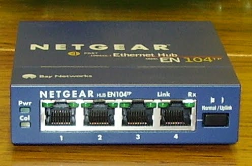
It is a simple device that allows to connect a few computers together. Look at the typical, cheap hub you can buy for home purposes:

Pic. 8 - An Ethernet Hub.

"How does the hub work then?" - I can tell my son got some interest by now.
"Well, that is the topic of our next lesson." - I say smiling.
;)

الثلاثاء، 7 أكتوبر 2014

Lesson 10 - Cisco Discovery Protocol

 Lesson 10 - Cisco Discovery Protocol

In the previous lesson we have explored how switches build their mac address table (aka Content Addressable Memory). It is critical to understand those concepts in order to perform troubleshooting related to connectivity issues.

In this lesson we'll continue studying layer 2 technologies. Today's theme is Cisco Discovery Protocol. This protocol comes in handy in many situations (trust boundary for Cisco IP Phones, auto qos and others).

What is Cisco Discovery Protocol?
CDP is Cisco proprietary layer 2 protocol. It is enabled by default on majority of Cisco devices including IP phones. It can work on any connections supporting SNAP (such as LANs, but also ATM and Frame-Relay). The only time you'll see the CDP turned off by default, is when you use frame-relay configured interfaces.

What does CDP do?

Every Cisco device using this protocol, reports information about itself by advertising special packets out of its all active interfaces. The important pieces of information it advertise include its:
  • Hostname
  • Platform
  • Ports where CDP packets are advertised
  • IOS version
  • IP address
CDP can help administrator discover Cisco devices connected and create a  topology diagram or prepare an inventory of the gear used. It can also be an additional tool in troubleshooting problems in the network. Working as a support technician, I found it useful numerous times.

Let's take a quick tour through the CLI (command line interface) and see what major commands CDP allows us to use and what they show.

I'm connected to my Cisco switch SW1 and in the privileged mode type in the following command:

Pic. 1

Using our best friend '?' we can see the CDP options. The last line '' stands for: 'carriage return'. A good, old-fashioned terminal lingo for 'press enter'. Let's try this first.

Pic. 2

Based on the output (Pic. 2) we see that CDP version 2 is enabled, the information packets (though technically should be called frames) are sent every 60 seconds. We also learn, that SW1 will keep CDP information it receives from its Cisco neighboring devices for 180 seconds (holdtime). Let's look at another CDP command:

Pic. 3

In the Pic. 3 we can see the traffic statistics such as CDP packets sent, received, any CDP encapsulation problems etc.

The below command (output in Pic. 4) will tell you which interfaces CDP is running on.
SW1#show cdp interface  
 
You can disable CDP on a specific interface or group of interfaces. For instance, if you do not want to run CDP on Fas0/1 interface, you could use the following command:
SW1#configure terminal
SW1(config)#interface Fas0/1
SW1(config-if)#no cdp enable

If you want to disable CDP on a group of interfaces you can use 'interface range' command. For instance, disabling CDP on Fas0/1, Fas0/2, Fas0/5 and Fas0/8 would look like this:
SW1#configure terminal
SW1(config)#interface range fas0/1 - 2 , fas0/5 , fas0/8
SW1(config-if-range)#no cdp enable

NOTICE
If you use the 'interface range' command, the consecutive ports can be specified with '-' but make sure your use 'space' before and after '-' (fas0/1 - 2). The same applies to non-consecutive ports (fas0/5 , fas0/8). There is 'space' before and after the comma character ','.


As you will see later, CDP discloses some vital information (e.g. IOS version), so for the security reasons you may decide to turn off CDP altogether. Be careful before you do that though, as some application may rely on this protocol. Disabling CDP can cause cascading problems in your network. The command which disables CDP completely (on all interfaces) is:
SW1#configure terminal
SW1(config)#no cdp run

Pic. 4

Now, let's see what neighboring devices SW1 discovered by listening to their CDP packets (Pic. 5).

Pic. 5 

Dissecting the Pic. 5 output we learn the following:
  • SW1 received CDP packets from the device named 'R1' (hostname).
  • This CDP packet was sent from R1's Fas0/0 interface (the last column 'Port ID').
  • SW1 received this CDP information packet on its Fas0/1 local interface ('Local Intrfce').
  • This leads us to a conclusion that R1's Fas0/0 interface is directly connected to SW1's Fas0/1 interface.
  • R1 neighbor is a router as the capability list shows 'R S I' (R=router, S=switching capability, I=IGMP support).
  • R1 is 2611XM platform.
That's not all by any means. There is another command we can use to obtain more information about R1. Click at the Pic. 6

Pic. 6

It shows you information about IOS version running on R1, as well as its IP address 192.168.10.254 configured on Fas0/0 interface. Now you understand why you might consider turning off CDP on some interfaces. You do not want to show such details to a third party company (like your service provider), that connect to your devices.

Instead of using 'show cdp entry R1', you can also use the following command that displays detailed (similar to Pic. 6) output about ALL discovered neighbors :
SW1#show cdp neighbor detail

In lesson 11, you will learn the commands related to switch mac-address-table which was covered in theory only (lesson 9). Also, we'll hone all our skills we have obtained so far. Things will begin to fall into place. At least that's my hope.

A practical application of the two last lessons below.

Lesson 3 - Initial Configuration of Cisco Switch and Router

Lesson 3 - Initial Configuration of Cisco Switch and Router

Understanding technologies requires a skill. Even though not mine, but the best definition of what a skill is, could be summarized in five words: knowledge and one thousand repetitions.

In this lesson, there is no real technology to explain. Instead, you will get familiar with some useful commands we use very often while configuring our routers and switches. This practical exercise however, is going to help hone your skills obtained in the previous lesson.

Take a look at our simple topology first:
Switch/router/computer icons designed by: Andrzej Szoblik - http://www.newo.pl

And here's our plan for the initial configuration. 
  1. Configure the host names on both the switch and the router (SW1 and R1 respectively).
  2. When you mistype the command in the 'enabled mode' the IOS is trying to resolve this name to ip address. Disable that name resolution.
  3. Protect the 'privileged exec mode' with clear text password. Use 'cisco_enable' as your password.
  4. Encrypt the password with 'over-shoulder' algorithm.
  5. Protect the access to the console port 0. Use 'cisco_console' as your password.
  6. Configure the console port 0, so it disconnects you after 5 min. 30 sec. of idleness.
  7. Configure the console port 0 such, that system messages sent to the screen, do not interfere with what you are typing.
  8. After careful consideration you decide to use the most secure access to the 'privileged exec mode'. Disable the previous method and configure the same password using MD5 algorithm to encrypt the password.
  9. On the switch assign ip address (use: 192.168.1.253/24) on the management interface Vlan 1.
  10. Configure the switch to use the default-gateway (address of the default gateway: 192.168.1.254/24) in case it is managed remotely from another subnet or network.
  11. Enable the router's interface FastEthernet1/0. Use 192.168.1.254/24 address.
  12. Enable the interface facing the Internet Serial0/1 (we pretend it is the public interface). Use ip address 172.31.1.1/30.
  13. Enable the remote access to your devices via telnet. Use password 'cisco_remote'.
  14. After careful consideration you decide to use ssh as the remote access method rather than telnet. Configure that.
  15. Save the configuration on both switch and the router so it is available after reload/power cycle.
Solution:
1. Configure the host names on both the switch and the router (SW1 and R1 respectively). 
Most of the steps are identical on a switch and a router.  That is why I'm presenting, router's configuration only. You have to repeat them on the switch yourself. If the configuration of the switch is different, it is presented as well (step 9 and step 10).

If your prompt shows the user mode '>' you must enter the privileged mode first by typing 'enable':
Router>enable
Router#

Then, in order to set the host name on the router you must enter the 'config mode' (you can abreviate the command to 'conf t'):
Router#configure terminal
Router(config)#

Finally, you type in:
Router(config)#hostname R1
R1(config)#

NOTICE!
The commands take effect immediately as long as their syntax is correct.


2. When you mistype the command in the 'enabled mode' the IOS is trying to resolve this name to ip address. Disable that name resolution. 

R1(config)#no ip domain-lookup

3. Protect the 'privileged exec mode' with clear text password. Use 'cisco_enable' as your password.
R1(config)#enable password cisco_enable

4. Encrypt the password with 'over-shoulder' algorithm.

R1(config)#service password-encryption

5. Protect the access to the console port 0. Use 'cisco_console' as your password.

In order to do that you have to change the context from 'config mode' to 'line console 0' mode. Pay attention to the prompt! The 'login' keyword is going to prompt the user for the password.

NOTICE!
the 'no login' command would allow the user to access the console 0 WITHOUT asking for the password even if one was configured.


R1(config)#line console 0
R1(config-line)#password cisco_console
R1(config-line)#login

6. Configure the console port 0, so it disconnects you after 5 min. 30 sec. of idleness.

We're still in console 0 prompt so, we can continue configuring console 0.

R1(config-line)#exec-timeout 5 30
R1(config-line)#

If you wanted the console line 0 to never disconnect you during the time of idleness, you would use:exec-timeout 0 0.

7. Configure the console port 0 such, that system messages sent to the screen, do not interfere with what you are typing.

By default, all system messages are sent to the console 0 and they may interfere with what you are currently typing on the console 0 line. If you are accessing the device via telnet/ssh (remotely), you do not see any messages. If you want to see them on the vty lines (remote connection via telnet/ssh), you must type in: 'terminal monitor' in the 'enabled mode'. Here is the command to satisfy the step 7 in our design:
R1(config-line)#logging synchronous

8. After careful consideration you decide to use the most secure access to the 'privileged exec mode'. Disable the previous method and configure the same password using MD5 algorithm to encrypt the password.

As we are still in the line console 0 context (look at the prompt), we need to step back to the 'config mode', and then remove the previous 'enable' password. Next we will proceed with md5 password configuration. If you did not remove the previous 'enable password', system is going to use the more secure one anyway.

R1(config-line)#exit
R1(config)#no enable password
R1(config)#enable secret cisco_enable

9. On the switch assign ip address (use: 192.168.1.253/24) on the management interface Vlan 1.

I assume that you have completed the steps 1-8 on BOTH router and switch. The commands and prompts will be identical. Now, you can assign ip address on Vlan 1 interface.
SW1>enable
SW1#conf t
SW1(config)#interface vlan 1
SW1(config-if)#ip address 192.168.1.253 255.255.255.0
SW1(config-if)#no shutdown

10. Configure the switch to use the default-gateway (address of the default gateway: 192.168.1.254/24) in case it is managed remotely from another subnet or network.

We need to step back to 'config mode' from interface Vlan1 mode to accomplish the task.
SW1(config-if)#exit
SW1(config)#ip default-gateway 192.168.1.254

11. Enable the router's interface FastEthernet1/0. Use 192.168.1.254/24 address.
R1(config)#interface f1/0
R1(config-if)#ip address 192.168.1.254 255.255.255.0
R1(config-if)#no shutdown


12. Enable the interface facing the Internet Serial0/1 (we pretend it is the public interface). Use ip address 172.31.1.1/30.

Even though we are currently in F1/0 interface context (look at the prompt), we can jump directly towards s0/1 without typing 'exit' first. If you use real routers (not dynamips), one end of the connection must use DCE cable and the other DTE cable. They are connected back-to-back and DCE interface must be set up with the clock rate.
R1(config-if)#interface s0/1
R1(config-if)#ip address 172.31.1.1 255.255.255.252
R1(config-if)#no shutdown

13. Enable the remote access to your devices via telnet. Use password 'cisco_remote'.

Remote access connections are service by special, virtual lines called vty. Here, we will use vty lines 0 through 4, allowing only five concurrent connections via telnet.
R1(config-if)#line vty 0 4
R1(config-if)#password cisco_remote
R1(config-if)#login

14. After careful consideration you decide to use ssh as the remote access method rather than telnet. Configure that.

This is going to be the most complex part in our lab. Below are four steps need to complete the task.

a) Configure system domain-name. Without the domain name, IOS cannot generate rsa keys used for encryption and decryption (public/private). The domain name can be any name you choose to use (here: ccna.local) but company's real name is a good idea.

R1(config-line)#exit
R1(config)#ip domain-name ccna.local
R1(config)#

b) When you type the below command the system will ask you what should be the length of the keys. Choose 1024 value. IOS will take a few seconds to generate them and automatically start SSH server. Wait till it's done.
R1(config)#crypto key generate rsa
R1(config)#

c) Create a user account that will be used for ssh access (here: user=admin, password=S3cr3t).

R1(config)#username admin password cisco_remote
R1(config)#

d) Enable ssh protcol and disable telnet on vty lines 0 4. Make sure that ssh will use locally created user (admin) for ssh connections. This is done using 'login local' command.
R1(config)#line vty 0 4
R1(config-line)#transport input ssh
R1(config-line)#login local
R1(config-line)#end
R1#

15. Save the configuration on both switch and the router so it is available after reload/power cycle.

R1#copy running-config startup-config 

الاثنين، 6 أكتوبر 2014

Lesson 2 - Navigating in Cisco IOS

Lesson 2 - Navigating in Cisco IOS

Once, you have connected to your Cisco switch or router console port, and power up the device you will see some information displayed during the start of the device. If the device has no initial configuration you are presented with:

Pic. 1 - System Configuration Dialog


You can safely cancel this request as its capability to configure the device is not very impressive. Instead, you are going to do things all professionals do: command after command.

What follows is bunch of messages sent to the screen and after hitting the Enter key few times you get something like this (here is the router, but a switch would introduce itself as ... Switch> ):
Router>

IOS Modes (contexts)

This prompt of the device tells you in which 'context' you are, and the one above with the '>' character is known as 'user exec mode' or 'privilege level 1 mode'. You can't configure much in this mode of operation. It is designed as a 'monitoring' mode not a 'configuration' one. Also, the monitoring capability is limited. For instance, you can't see the running configuration of the device.

Type in the following command:
Router>enable
Router#

The prompt changes to '#' which is called 'privileged exec mode', 'enabled mode' or sometimes 'privilege level 15 mode'. I would like to draw your attention to two things here. Both modes of operation (or contexts, if you like) have two things in common:
  1. They are used primarily to monitor the device (you will be using 'show' and 'debug' commands in those modes).
  2. They are context for immediate execution of your commands. If the syntax is correct, system executes the command immediately.
Those two modes differ from one another as well:
  1. User Exec Mode - is limited in terms of what information will be available.
  2. Enabled Exec Mode - gives the operator ALL information (like root or Administrator account on a computer).
Question Mark 

As the commands take many attributes your best friend is the question mark '?'. This help is known as the 'context-sensitive help'. This means that depending on which context you use, while typing a question mark (?) the system is going to list the commands that can be executed in that particular mode of operation. See more in the attached video.

Configurations

In order to configure things in Cisco IOS (except for some minor changes), you must enter the 'global configuration mode' first which is characterized by the following prompt:
Router(config)#

This context can be accessed by typing the following command in the 'privileged exec mode':
Router#configure terminal

Whatever you configure this particular mode it is going to be applied to the device as a whole unit(e.g. hostname, default gateway on a switch etc.).

If you want to enter the context of the interface to configure it with some parameters like ip address, speed, duplex, description etc. , you must enter that interface from the global configuration mode like the one below:
Router(config)#interface fastethernet1/0

If you do not know what interfaces your device has, type the following command in the enabled mode:

Router#show ip interface brief

As you see, in the 'global configuration mode' I did the following actions in order to access the context of the interface:
  1. Entered the interface type (here: Fast Ethernet).
  2. Referenced the module number (here: 1)
  3. Referenced the port number in the module 1 (here: 0)
Please, note that routers count ports starting from 0, switches starting from 1.

You'll learn other contexts as we go through numerous labs and video presentations.

Abbreviations

You don't have to type in the full words of the commands and certain attributes that follow the commands. For instance, instead of typing:
Router#configure terminal
Router(config)#

You can type:
Router#conf t
Router(config)#

As long as the abbreviation uniquely describes which command you want to use, the system has no problem accepting it.

Shortcuts And Keystrokes

When you type enough of the characters that uniquely identify the command in a given context you can use 'tab' key and the system is going to complete the command on the screen for you (just like in Linux).

I often use the following keystrokes while editing the commands:
  • CTRL-z - takes the cursor back to the 'enabled exec' mode from any other context
  • CTRL-a - takes the cursor to the beginning of the line
  • CTRL-e - takes the cursor to the end of the line
  • CTRL-k - erases everything to the right of the cursor
  • CTRL-u - erases everything to the left of the cursor
  • Upper Arrow or CTRL-P - displays previous command from the history buffer
  • Lower Arrow or CTRL-N - displays next command from the history buffer
System keeps the record of up to ten (default) commands you typed in. You can increase/decrease the history buffer up to 256 commands.

If you want to check the history buffer size, type in:

Router#show terminal | include history

Changing the buffer size can be accomplished with the following command in the 'enabled mode'
Router#terminal history size 256

The above command  will increase the size of the history buffer to 256 commands.

If you want to see the buffer (which commands were typed) use this command:

Router#show history
    Please, take a look at the video I posted below to see most of those things in action. Practice them until you are confident with the content of this lesson before you proceed to the next one.

    Next lesson is going to be about creating an initial configuration of our router and/or switch.

    Lesson 1 - Connecting to Cisco Console Port with MINICOM


    Cisco is easy. If I could learn it, anybody can!
     
    If you are a linux user user you must learn how to connect to your Cisco router or switch using roll-over cable (the cable that comes with your device).

    Step1 - Installing Minicom

    Linux users will use application called 'minicom'.  If you are Ubuntu user you can install it using either 'Synaptic Package Manager' or type in the following in your terminal window:
    $ sudo apt-get install minicom

    Once it is installed, you must configure the 'minicom' to communicate with the console port of your router/switch.

    Step 2 - Connection to Console Port

    Power up your router/switch and connect the roll-over cable to your computer's serial port (DB-9) and to the 'console' port of your router/switch (RJ-45).

    Step 3 - Configure Minicom

    Open your Terminal window (Applications ==> Accessories ==> Terminal) and type in:

    $ minicom -s


    Scroll down to 'Serial Port Setup' and hit Enter:
    Pic. 1

    Choose 'A' to set up the serial port of your computer (here the first serial port is referenced as ttyS0) so it reads as highlighted below. Then hit Enter again to accept the change:
    Pic. 2

    Next, press 'E' and then 'C' again to access the transmission speed and change it to '9600' value (no apostrophies). You should see values like highlighted below:
    Pic. 3


    Then hit Enter twice to get back to the first screen (Pic.1)

    The last thing is to save this configuration (you can choose 'dfl' to be the default template or with some other name).
    Pic. 4
      

    If you chose 'dflp and then, 'Exit from Minicom', you can try out your work now. Type in:
    $ minicom

    and hit Enter

    You should see the console prompt of your router/switch. If you want to leave the minicom use CTRL-A keystroke and then type 'x' and confirm you want to leave the application.