chitika2

‏إظهار الرسائل ذات التسميات Protocols. إظهار كافة الرسائل

الأحد، 23 نوفمبر 2014

Lesson 23 - Introduction to Rapid STP (802.1w)

Lesson 23 - Introduction to Rapid STP (802.1w)

Good news is that if you have learned 802.1d protocol (STP standard), only few things change in terms of the terminology and operation in the Rapid Spanning-Tree Protocol. RSTP is clearly an evolution of the regular STP but definitely NOT the revolution. The three phases of operation mentioned in lesson 20 still apply. 

This post is going to be the last in the series on Spanning-Tree Protocol fundamentals.

Let's focus on the major changes introduced in RSTP by comparing it to the standard STP.
  • STP Port States: "disabled", "blocking", "listening" are renamed to DISCARDING inRSTP. As far as the "forwarding" state, the name remains unchanged.
  • STP Port Roles: designated and root roles are still the same. But the non-designated role has been split in two new ones: ALTERNATE and BACKUP roles in RSTP.
Below picture will give you an indication as to what they describe.
Pic. 1 - Rapid STP Alternate Port.

Icons designed by: Andrzej Szoblik - http://www.newo.pl

An alternate port is a port that is in a blocking state and receives superior (better) BPDU frames from another switch. The port F0/2 of SW2 is the example of alternate port.
Pic. 2 - Rapid STP Backup Port.
Icons designed by: Andrzej Szoblik - http://www.newo.pl
backup port is a port in the blocking state that receives superior BPDU frames from the same switch like shown in Pic. 2. The port F0/3 of SW3 is the example of backup port.

Cisco STP Enhancement such as: spanning-tree uplinkfast and spanning-tree backbonefast are no longer used (except for spanning-tree portfast which Cisco still maintain in the IOS as an edge port). They have been replaced with negotiations of the port state that is based on the previously unused flags in the BPDU frame and a different mechanism of sending BPDU frames. The flags are shown below (pic. 3).

Pic. 3 - BPDU Flags.
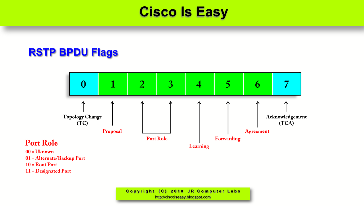
Understanding the nuts and bolts of the RSTP operation is beyond the scope of this tutorial. All you need to know at this stage is the terminology and benefits of using it over a legacy STP. The major advantage of RSTP is that switches use BPDU frames differently than before. Ports, upon first connection or when topology changes, exchange BPDUs with proposal/agreement flags set helping achieve fast transition to the appropriate state. They negotiate whether the port should be the designated, non-designated or root port role. If the port becomes the root port, all other ports begin negotiation by exchanging proposal/agreement BPDUs since the path towards the root bridge is different. It is extremely fast mechanism that speeds up the convergence upon a topology change.

A few other changes implemented in RSTP you must be aware of are as follows.
  • All switches exchange BPDUs instead of relaying them after they have received them from the root bridge. BPDUs have become a true keepalive mechanism. The switches do not have to wait for the root bridge to notify them about topology change that occurred somewhere in the network. A switch that detects change notifies its neighbors about it. And those in turn, notify their neighbors immediately. It is a mechanism similar to OSPF updates in that respect.
  • RSTP is backward compatible with STP (802.1d) speaking switches. Upon receiving BPDU version 1 (802.1d), the port transitions to the legacy STP protocol. All timers (max_age, forward_delay) are used according to the STP specifications (802.1d).
There are also two new concepts introduced in RSTP that are worth mentioning:
  1. Edge Port - which is something you are already familiar with. It is the port that is the candidate for a quick transition to forwarding state as it connects device that cannot create the loop (no BPDUs received on that port). Cisco enables Edge Port capability by using spanning-tree portfast feature described in the previous lesson. The ports must be a point-to-point link type (full duplex).
  2. Link Type - the type of the link is derived from the duplex of the port:
  • Full Duplex = Point-to-Point link
  • Half Duplex = Shared link
All these changes serve one purpose: they help in fast convergence on a detection of the new connection or/and a topology change. The speed of convergence is similar to the one when Cisco STP Enhancements are used in STP. The difference is that now fast convergence is accomplished as an industry standard mechanism, not a proprietary solution.

The configuration of RSTP is pretty straightforward.
SW(config)#spanning-tree mode rapid-pvst

That is it!

Deterministic election of the root bridge and all the jazz related to it explained in the previous lesson are identical.

If you want to learn more on RSTP operation google it by using this query:
understanding rstp. You'll find a plethora of documents out there.

الجمعة، 21 نوفمبر 2014

Lesson 21 - Spanning-Tree Protocol in Practice

Lesson 21 - Spanning-Tree Protocol in Practice

Previous post was designed to present in a nutshell the STP operation. However, without some practice it's just academic knowledge. I think it is a good idea to look at the same concepts using real equipment. Here goes...

The below topology (pic. 1) uses redundant links which create the loops.
Pic. 1 - Network Topology
Icons designed by: Andrzej Szoblik - http://www.newo.pl

If there's one thing the administrator should do with such design, that would be configuring the root bridge. Typically, the most powerful switch in the center of the network plays that role. You do not want some access switch to be transmitting the frames between other switches. Access switches are designed to connect your computers to the network, and not to handle the majority of the traffic between the switches which root bridge must deal with.

If you do not configure root bridge yourself, the switch with the lowest MAC address becomes the root since the priority is identical on all of them by default. We do not want to leave it to a chance, do we? For simplicity reasons I have chosen to make SW1 my root bridge. There are at least two ways to configure this.
Method 1
I can manually decrement the priority on SW1 and leave the default value on the other switches. I want to make SW1 my root bridge for all the VLANs I use in my network (remember Cisco uses PVST+). The lowest priority value allowed is zero and if higher needs to be used, it must be an increment of 4096. If you type in the value that is not allowed, the system will present you with the list of values you can use.

Step 1
Check the VLANs configured.


Step 2
Make SW1 the root bridge for all the VLANs configured in the network by decrementing the default value. Here, I will use the value of '0'.


A quick verification if the command took effect is below:


 The above output confirms that SW1 has been elected as the root bridge:
 This bridge is the root

Familiarize yourself with the output of this command. All active ports of the switch are in designated role (forwarding state) as it is the root.

Also, notice that both Bridge ID and Root ID are the same values. I assigned priority of 0, but the system extended ID (PVST) adds VLAN number to the priority assigned. Thus, the priority 0 + (VLAN id) 500 = 500.
Priority: 500
MAC: 000b.5ff7.a080


Like mentioned before, if the priority value configured is not configured according to the allowed values, the system shows the numbers you can use:


Method 2
I can use the spanning-tree vlan root primary macro command which decrements the priority value using Cisco best practices.


Step 1
Check the VLANs configured like before.


Step 2
Make SW1 the root bridge for all the VLANs configured in the network by using the macro command.


And now comes the interesting bit. Having elected the root bridge SW1, I can predict all the rest of the process. Lesson 20 provides us with all the knowledge we need to posses to tell which ports will become root ports on SW2 and SW3 as well as which ports will be designated and which will be non-designated in our topology.

Can you do that on your own? 

The base MAC addresses on SW2 and SW3 are as follows (priority is default):
SW2 MAC: 000E:83DA:7580
SW3 MAC: 000D:28BF:FD40

If you want to check what is the base mac address on your switch type in:
SW#show version | include Base

At least give it a shot before you click at the pic. 2 below to check your answers. If you cannot do it yet, do not worry. I will guide you through the process using some powerful 'show' commands.
Pic. 2 - Spanning-Tree Topology Computed

Icons designed by: Andrzej Szoblik - http://www.newo.pl

There are two loops in my network. One between SW1 and SW2 using ports F0/13 and F0/14. The other loop is formed between SW3 connections to SW1 and SW2 (ports F0/15 and F0/16).

Let's look at SW2 first and see how the knowledge from lesson 20 applies here.

SW2 receives BPDU frames from SW1 on F0/13 and F0/14 ports and from SW3 on its F0/16 port. A closer look at the following output can be very informative.

The above output shows clearly which machine is the root bridge (000B:5FF7:A080). SW2 chose F0/13 as it Root Port. As you recall the first thing to check to determine which is the best path towards the root bridge (root port) is the accumulative cost towards the root. SW2 has three outgoing ports towards the root bridge as shown in the next output:

The accumulative cost is calculated by adding two values:

Port path cost + designated path cost.
  • Port path cost - arbitrarily set values by IEEE (the speed-to-cost table is shown in the previous lesson).
  • Designated path Cost - the cost towards the root bridge advertised by the neighboring switch.
Port F0/16 can be ruled out immediately since 'port path cost' (19) +  'designated path cost' (19) amounts to: 38.

As for the two remaining candidates to become a root port (F0/13 and F0/14), the total path cost is19 in both cases (19+0). We need to resort to the second test in our algorithm to break the tie: the lowest bridge id of the BPDU sender. Unfortunately, both ports receive BPDU frames from the same switch: SW1 (look at the previous output).
Designated Bridge has priority 500, address 000B:5FF7:A080

Next step to solve the issue is checking the port priority of the sender. But both ports F0/13 and F0/14 receive the same port priority (port id):
Designated port id is 128

The number of the port is not factored in, only the id value like shown above.

There is only one more thing that can help us determine which of these two ports should be the root port: the lowest port id of the receiver (SW2). F0/13 is lower in value than F0/14, so the former becomes the root port.

In the same way SW3 chooses its root port F0/15 as the root port since the accumulative cost using it is 19 as opposed to port F0/16 which total cost out towards the root bridge is 38.

Port F0/14 on SW2 becomes non-designated port (NDP) due to the fact, that the root bridge (SW1) has to have all the ports in designated mode which means they cannot be blocked.

The last thing to compute the STP active paths is to select the designated port between SW2(F0/16) and SW3 (F0/16). Again, the same formula solves the issue. As both SW2 and SW3advertise the same cost: 19, the tie breaker is going to be the lowest bridge id of the sender. In this contest, SW2 has higher bridge id (less preferred) which is: priority 33268, address 000E:83DA:758

SW3 priority being lower wins. SW3 bridge id for the same VLAN 500 looks like shown below:


priority 33268, address 000D:28BF:FD40

STP selects the layer 2 paths between the switches. In the pic. 2 I showed you also that all the ports connected to PC1PC2 and R1 are in a designated role. This is because those ports do NOT receive BPDUs. They automatically become designated (forwarding state).

As the last thing in this lesson, I'd like to ask you two questions.

Assuming that SW1 is the root bridge:

Question1
What would you need to reconfigure in our topology (pic. 1), for SW2 to choose F0/14 as the root port for VLAN 500?

Question 2
What would you need to reconfigure in our topology (pic. 1) for SW3 to choose F0/16 as the root port for VLAN 500?

NOTICE!
The method of choosing root port/designated port in the previous lesson holds the answers to these questions. Remember about the order of operation.


The answer to question 1
Since the cost is the same towards SW1 (root), we could modify it on SW2 with the following command:
SW2(config)#interface f0/13
SW2(config-if)#spanning-tree vlan 500 cost 20

This way I have increased the cost on this port to 20, and F0/14 cost now is lower (19).

Another method could be to change the port priority on the SW1 preferring port F0/14. This is how you could do it:
SW1(config)#interface f0/14
SW1(config-if)#spanning-tree vlan 500 port-priority 64

Since, the path cost towards the root are identical on both ports, bridge id of the sender is the same switch SW1, the third thing to influence which one to use is the port priority assigned by the BPDU sender (here SW1). This is shown in the following picture taken from SW2 (show spanning-tree vlan 500 detail):

Now, the priority imposed by SW1 on SW2's F0/14 is lower: 64 compared to port F0/13 which is128. Port F0/14 becomes the root port.

Answer to question 2
In order to change the root port on SW3 the only way to do that is to increase the cost to reach the root bridge on F0/15. For instance you could configure the following:
SW3(config)#interface f0/15
SW3(config-if)#spanning-tree vlan 500 cost 39

Since the total cost towards SW1 (root) using port F0/15 is 39 now, and using port F0/16 the cost used equals 38, this configuration will do the job.

Did you have fun? I sure did ;)

الثلاثاء، 18 نوفمبر 2014

Lesson 20 - Spanning-Tree Protocol Operation

Lesson 20 - Spanning-Tree Protocol Operation

In my previous post I tried to stress the need for redundant connections between the switches. Multiple paths help us avoid a single point of failure in our designs. However, adding new connections inevitably create loops causing multiple problems. The last section of lesson 19presented the solution: Spanning-Tree Protocol. It's time we learn a bit more about Spanning-Tree Protocol terminology and scrutinize its operation. So hold down to your hats as we begin the ride ;)

In order to understand the nuts and bolts of Spanning-Tree Protocol (STP), we need to get familiar with its terminology first.

Spanning-Tree Protocol Terminology
The ports participating in STP play different roles and those roles use different states of operation.
Spanning-Tree Port Roles
  1. Root Port (RP) - It is a port on a non-root switch, which is the shortest (the best) path towards the root bridge. Root bridge does NOT have any root ports. (no shortest path to itself ;-))
  2. Designated Port (DP) - It is a port that is in the forwarding state. All ports of the root bridge are designated ports (they are never in a blocking state). BPDU frames our sent out this port.
  3. Non-Designated Port (NDP) - It is a port that is in a blocking state in the STP topology.
Spanning-Tree Port States
  1. Disabled - The port in this state does not participate in the STP operation (it is shut down).
  2. Blocking - The port does NOT forward any Ethernet frames, does NOT accept any Ethernet frames (discards arriving frames), does NOT learn any MAC addresses. However, the portDOES process BPDU frames received from a neighboring switch. If the port transitions to this state (blocking), it can stay blocked for 20 seconds by default (max_age)
  3. Listening - The port in this state CAN send and receive the BPDU frames. However, the port in this state does NOT learn any MAC addresses, and does NOT forward or process incoming frames either. All Ethernet frames are being discarded. The computation of loop free topology takes place in this state. If the port transitions to this state (listening), it can stay in this state for 15 seconds by default (forward_delay).
  4. Learning - The port in this state already knows its role (root port or designated port ) in the STP domain. However, the port will not forward any Ethernet frames yet. It will be learning MAC addresses from the frames arriving at the port in order to populate MAC address table. This helps avoid too much flooding when the port transition to the forwarding state. If the port transitions to this state (learning), it can stay in this state for 15 seconds by default (forward_delay).
  5. Forwarding - The port in this state will forward all Ethernet frames as per switch operation. Also, the port will process all incoming Ethernet frames and will actively learn MAC addresses from the arriving traffic.

NOTICE!
Bridges and switches are functionally the same devices. I will use both terms interchangeably.


As soon as you familiarize yourself with STP port roles and port states, it is time to explain how Spanning-Tree Protocol works.
Pic. 1 - STP Port Terminology
Icons designed by: Andrzej Szoblik - http://www.newo.pl

STP (IEEE 802.1d) Principles of Operation
STP will use three stages to compute loop free topology (pic. 2):
  1. Single root bridge election.
  2. Each non-root switch to select a single best port towards the root (root port).
  3. Each non-root switch to select a single forwarding port per segment (designated port).
 Pic. 2 - STP Overview
Icons designed by: Andrzej Szoblik - http://www.newo.pl

Bridge Protocol Data Unit (BPDU)
All switches communicate with one another using special frames called BPDU. Those frames contain multiple parameters that switches are going to process in order to create and maintain loop free topology.

Root Bridge
Root bridge is the switch that has all ports working in the designated role. It will be the reference point from which the loop free topology is computed. Root bridge will impose the timers that other switches will use such as: 
  • hello time - how often BPDUs are going to be sent/relayed (default timer=2 seconds), 
  • max age - how long the configuration is valid (default timer=20 seconds),
  • forward delay - how long a port should be in listening/learning state (default timer=15 seconds). 
Root bridge will be announcing its presence by sending BPDU frames. Other switches will relay those frames out their designated port given the hello time. Also, the root bridge has all its ports in the designated role (forwarding).

1. Root Bridge Election

Only one switch in the layer 2 network becomes the root bridge. This is how standard was defined and is known as the Common Spanning-Tree approach (CST). Cisco changed that paradigm and introduced Per Vlan Spanning-Tree approach (PVST+). Cisco switches elect a single root switch per VLAN so, in theory each VLAN could have its own root bridge.

Root election is based on a single parameter that is found in the BPDU frame called: Bridge ID. The switch with the lowest Bridge ID becomes the root. Bridge ID has the following format:
priority.base-mac-address

Priority is configurable parameter that is used to elect the root bridge a device you want to be the root. The default value is: 32768. The lower the value is the more likely for a switch to become a root.

Base Mac Address is the unique mac address every switch has been given by the manufacturer. It is a tie breaker in case the priority on all switches is identical.

If you've understood everything so far, you're ready to look at the election process in more detail.
Pic. 3 - Root Bridge Election.
Icons designed by: Andrzej Szoblik - http://www.newo.pl

Imagine that we've just wired our topology in the pic. 3. Now, we start up all the switches and as soon as their ports transition to LISTENING state, they begin to send BPDU frames out of all active ports. In those frames both Bridge ID and Root ID parameters point to their own priority.base-mac-address value. In other words, each switch thinks it is the root bridge. It is like each switch is saying: "Hi there! This is my name (Bridge ID) and by the way I'm the root (Root ID the same as the Bridge ID value). Since they are processing the incoming BPDU's from the neighbors, SW2 andSW3 realize that SW1's Bridge ID is lower than theirs. From that point onwards, they begin to relay BPDU frames saying that SW1 as the root bridge.

In our example, SW3 upon receiving the BPDU from SW1SW2 and SW4  compares their Bridge ID with its own and the conclusion is that SW1's Bridge ID has the lowest value (base-mac-address breaks the tie). From this point onwards, it relays the BPDU frame out of all its active ports with the following parameters:
Bridge ID = 32768.0000.3333.3333
Root ID = 32768.0000.1111.1111

Similarly, all the switches agree that SW1 is the root (their own Bridge ID is higher).

2. Root Port Selection

As soon as the root has been elected, all non-root switches begin to calculate which port is the best (the least cost) towards the root bridge. This port will be called the root port.
Pic. 4 - Root Port Selection
Icons designed by: Andrzej Szoblik - http://www.newo.pl
SW2SW3 and SW4 receive BPDUs from different directions. For instance, SW2 will receive them on its port F0/1 and F0/2 (look at pic 4). The accumulative cost (the sum of the cost in the path towards the root), is taken into consideration. The lowest cost to reach the root becomes the root port.

How the cost of path is calculated?

Each speed has its arbitrarily assigned cost which is configurable. A few examples are below:

10 Mbps = 100
100 Mbps = 19
1 Gbps = 4
10 Gbps = 2

The root bridge (here SW1) is sending its BPDU frame every 2 seconds. It uses the parameter called: Root Path Cost in BPDU to advertise the cost to the root. It puts the value of '0' in it, as it is the root bridge and has no cost to itself. The frame is sent out its port F0/1 towards SW3 and F0/2 towards SW2SW2, upon receiving it, adds the cost used to reach the sender of BPDU based on the predefined speed-to-cost value (all ports in our topology are FastEthernet=19).

Root Path Cost = 0 + 19 = 19 via F0/2

SW2 is going to advertise its best (as of now) cost out of F0/1 port towards SW3SW3 will receive BPDU from SW1 with the Root Path Cost=0 on its F0/1 port. It will also receive BPDU from SW2on its F0/2 interface with the Root Path Cost=19. As both ports have the cost of 19 towards those BPDU senders, the following math is done to choose the least cost path towards the root bridge:

Root Path Cost = 0 + 19 = 19 via F0/1
Root Path Cost = 19 + 19 = 38 via F0/2

It is clear that the direct connection towards root bridge via F0/1 is going to be selected as the root port.

SW3 has the least cost towards equal 19 (via F0/1 port). This cost is going to be added to Root Path Cost while it sends the BPDUs out F0/2, F0/3 and F0/4. Of course, SW2 also chooses its F0/2 port as the root port since the cost is smaller.

What if the Root Cost Path is identical?

We run into that situation on SW4. It receives BPDUs on its ports F0/1 and F0/2 with the following parameters:

Bridge ID = 32768.0000.3333.3333
Root ID = 32768.0000.1111.1111
Root Path Cost = 19

The cost clearly does not help to choose a single root port as both ports have the same cost:
19 + 19 = 38.

The following algorithm is used to determine the root port or designated port (in order):
  1. Prefer the lowest Root Path Cost.
  2. In case of the same Root Path Cost, prefer the lowest Bridge ID of the designated switch (the neighbor that sends BPDUs).
  3. In case of receiving BPDUs on multiple ports from the same designated switch (BPDU sender), prefer the lowest Port ID (known also as port priority) of the sender. That parameter has a default value 128 and is configurable.
  4. In case of all above are did not resolve the problem, prefer the lowest Port ID of the BPDU sender.
Equipped with that knowledge let us consider SW4 now.
  1. SW4 receives BPDUs on port F0/1 and F0/2. The Root Path cost is the same: 19 + 19 = 38 on both ports.
  2. The designated switch (SW3), is the same switch i.e. the same Bridge ID (32768.0000.3333.3333).
  3. The designated switch (SW3) sends BPDUs out of its F0/3 and F0/4 ports with the same priority = 128 (Port ID).
  4. The tie breaker is the lowest Port ID where BPDU frames arrive on SW4. Port f0/1 becomes the root port since F0/3 is lower than F0/4 on SW3.
The root ports have been selected on all non-root switches (pic. 5). STP will select a single designated port (forwarding) per segment to block the redundant path towards the root bridge. This way the loop does not exist. Should any of root ports fail, it will take around 30-50 seconds to put the blocking port into forwarding state.

3. Designated Port Selection.
This procedure follows exactly the same algorithm used for root port selection.
Pic. 5 - Designate Port Selection
Icons designed by: Andrzej Szoblik - http://www.newo.pl

Since root port is the best port towards the root bridge it is going to be in the forwarding state (look at the beginning of this lesson). What is left to do, is to choose one of the ports between SW2 andSW3 as designated (forwarding) and the other as non-designated (blocked). The same applies between SW3 and SW4. Either SW3 will block its F0/4, or SW4 should block its F0/2 port.

SW3 will block its F0/2 (non-designated) and SW2 will make its F0/1 port designated (forwarding). The process will look as follows:
  1. Root Path Cost advertised by SW2 is 19 and so is the cost advertised by SW3.
  2. SW2 has lower Bridge ID (32768.0000.2222.2222) than SW3 (32768.0000.3333.3333). SW3must block its F0/2.
And last selection is going to happen between SW3 (port F0/4) and  SW4 (port F0/2).
  1. Root Path Cost Advertised by SW3 is 19, but SW4 advertises its cost as 38 (two hops via F0/1). SW4 blocks its port F0/2 (non-designated), the SW3 promotes its port F0/4 to designated role (forwarding).
Pic. 6 - Spanning-Tree Topology Computed
Icons designed by: Andrzej Szoblik - http://www.newo.pl

This process happens in the LISTENING state of all ports. Since the topology has been computed and does not have loops (blocking appropriate ports), it is safe to move to next states: learning and finally forwarding.


In the next post, we will look at this process one more time using command line interface and real equipment.

الأحد، 26 أكتوبر 2014

Lesson 10 - Cisco Discovery Protocol

Lesson 10 - Cisco Discovery Protocol

In the previous lesson we have explored how switches build their mac address table (aka Content Addressable Memory). It is critical to understand those concepts in order to perform troubleshooting related to connectivity issues.

In this lesson we'll continue studying layer 2 technologies. Today's theme is Cisco Discovery Protocol. This protocol comes in handy in many situations (trust boundary for Cisco IP Phones, auto qos and others).

What is Cisco Discovery Protocol?
CDP is Cisco proprietary layer 2 protocol. It is enabled by default on majority of Cisco devices including IP phones. It can work on any connections supporting SNAP (such as LANs, but also ATM and Frame-Relay). The only time you'll see the CDP turned off by default, is when you use frame-relay configured interfaces.

What does CDP do?

Every Cisco device using this protocol, reports information about itself by advertising special packets out of its all active interfaces. The important pieces of information it advertise include its:
  • Hostname
  • Platform
  • Ports where CDP packets are advertised
  • IOS version
  • IP address
CDP can help administrator discover Cisco devices connected and create a  topology diagram or prepare an inventory of the gear used. It can also be an additional tool in troubleshooting problems in the network. Working as a support technician, I found it useful numerous times.

Let's take a quick tour through the CLI (command line interface) and see what major commands CDP allows us to use and what they show.

I'm connected to my Cisco switch SW1 and in the privileged mode type in the following command:

Pic. 1

Using our best friend '?' we can see the CDP options. The last line '' stands for: 'carriage return'. A good, old-fashioned terminal lingo for 'press enter'. Let's try this first.

Pic. 2

Based on the output (Pic. 2) we see that CDP version 2 is enabled, the information packets (though technically should be called frames) are sent every 60 seconds. We also learn, that SW1 will keep CDP information it receives from its Cisco neighboring devices for 180 seconds (holdtime). Let's look at another CDP command:

Pic. 3

In the Pic. 3 we can see the traffic statistics such as CDP packets sent, received, any CDP encapsulation problems etc.

The below command (output in Pic. 4) will tell you which interfaces CDP is running on.
SW1#show cdp interface  
 
You can disable CDP on a specific interface or group of interfaces. For instance, if you do not want to run CDP on Fas0/1 interface, you could use the following command:
SW1#configure terminal
SW1(config)#interface Fas0/1
SW1(config-if)#no cdp enable

If you want to disable CDP on a group of interfaces you can use 'interface range' command. For instance, disabling CDP on Fas0/1, Fas0/2, Fas0/5 and Fas0/8 would look like this:
SW1#configure terminal
SW1(config)#interface range fas0/1 - 2 , fas0/5 , fas0/8
SW1(config-if-range)#no cdp enable

NOTICE
If you use the 'interface range' command, the consecutive ports can be specified with '-' but make sure your use 'space' before and after '-' (fas0/1 - 2). The same applies to non-consecutive ports (fas0/5 , fas0/8). There is 'space' before and after the comma character ','.


As you will see later, CDP discloses some vital information (e.g. IOS version), so for the security reasons you may decide to turn off CDP altogether. Be careful before you do that though, as some application may rely on this protocol. Disabling CDP can cause cascading problems in your network. The command which disables CDP completely (on all interfaces) is:
SW1#configure terminal
SW1(config)#no cdp run

Pic. 4

Now, let's see what neighboring devices SW1 discovered by listening to their CDP packets (Pic. 5).

Pic. 5 

Dissecting the Pic. 5 output we learn the following:
  • SW1 received CDP packets from the device named 'R1' (hostname).
  • This CDP packet was sent from R1's Fas0/0 interface (the last column 'Port ID').
  • SW1 received this CDP information packet on its Fas0/1 local interface ('Local Intrfce').
  • This leads us to a conclusion that R1's Fas0/0 interface is directly connected to SW1's Fas0/1 interface.
  • R1 neighbor is a router as the capability list shows 'R S I' (R=router, S=switching capability, I=IGMP support).
  • R1 is 2611XM platform.
That's not all by any means. There is another command we can use to obtain more information about R1. Click at the Pic. 6

Pic. 6

It shows you information about IOS version running on R1, as well as its IP address 192.168.10.254 configured on Fas0/0 interface. Now you understand why you might consider turning off CDP on some interfaces. You do not want to show such details to a third party company (like your service provider), that connect to your devices.

Instead of using 'show cdp entry R1', you can also use the following command that displays detailed (similar to Pic. 6) output about ALL discovered neighbors :
SW1#show cdp neighbor detail

In lesson 11, you will learn the commands related to switch mac-address-table which was covered in theory only (lesson 9). Also, we'll hone all our skills we have obtained so far. Things will begin to fall into place. At least that's my hope.

A practical application of the two last lessons below.